
STRUCTURAL STRESS ANALYSIS ON THE RUBBER DIAPHRAGM OF AIR-OPERATED VALVE
Air-operated valves are used extensively in the power-generation industry for process control and system isolation functions. A study on the prevention of damage to an air operated valve is very important. Especially, the diaphragm in an actuator of an air-operated valve has the highest damage rate.
In this study, the stress of diaphragm with thickness change is analyzed. For this analysis, four experiments were conducted to obtain material properties of rubber. A stress analysis is carried out by commercial FEM code, ANSYS 8.0. It is compared with tension test to verify finite element analysis. From the result of the analysis, the maximum stress happened at flange edge part, and the maximum displacement happened between flange edge and spring support. This study also finds out the effect of the thickness about variable thickness. Even if a section area is same, the maximum stress is varied with the thickness of edge side.
1.Introduction
Air operated valves are used extensively in the power-generation industry for process control and system isolation functions. Nuclear power plants consist of many air-operated valves. Safety is a primary issue in a nuclear power plant. A study on the prevention of failure of an air-operated valve is very important. The most critical and sensitive component of the air-operated valve is the diaphragm. This provides the seal that allows a successful actuation to overcome spring pressure that is used to return the valve to its "safe" position.Table 1 shows failure cases of air operated valves. Table 1 is referred to "Air-operated valve maintenance guide"[l]. From the Table.1, 30% of total damage is a failure of the actuator. Of actuator failures, the highest failure (35%) was diaphragm failures, the second failure (29%) was seal and seal, the third highest failure (13%) was bolting- related failures, and next (4%) was piston binding.
In this study, structural stress analysis on the rubber diaphragm is carried out by commercial FEM code.
2.Structural Stress Analysis
2.1. Model of analysis
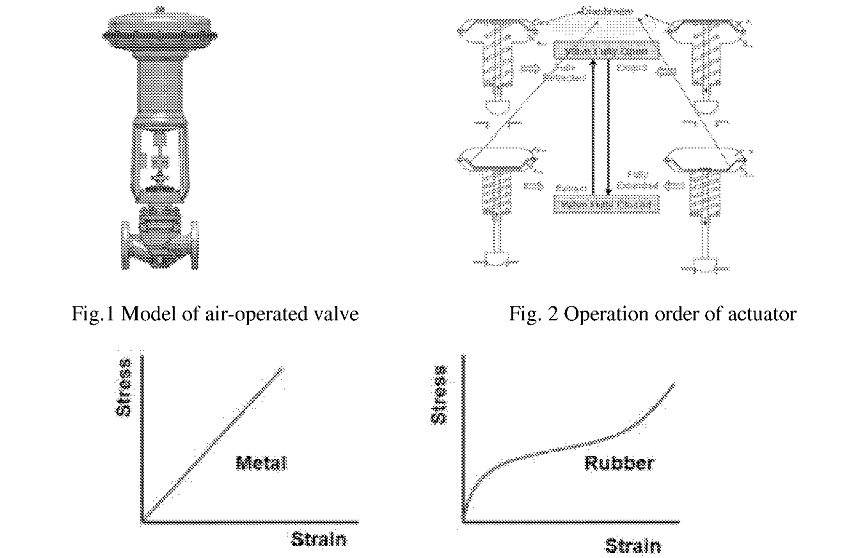 Fig. 3 The comparison of linear elastic and hyper elastic for metal and rubber material
[a| Stress -strain curve for metal material
[b] Stress-strain curve for rubber material
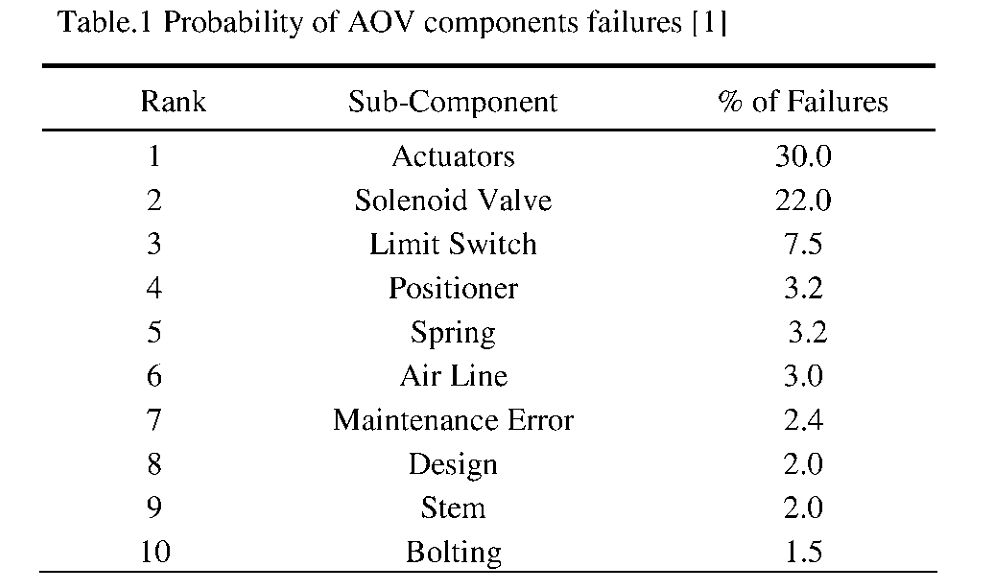
Fig. 1 shows a 2-inch globe type air-operated valve. The shape and operating order of the actuator are shown in Fig.2. The diaphragm pushes the support plate by pressure imposed at the top. The support plate is supported by spring. The support plate budges stem, and the valve gets closed by movement of the stem. If the pressure of the actuator is removed, the support plate is initialized by the force of spring. The failure of the diaphragm is fatal to the function of the air-operated valve. Major material of diaphragm is rubber. The modulus of elasticity of engineering steel is 210 GPa, but rubber is 0.7-4.0 MPa. Rubber has nonlinear properties in stress-strain relation. This is shown in Fig.3. The material properties of rubber are obtained by mechanical test applied to finite element analysis.
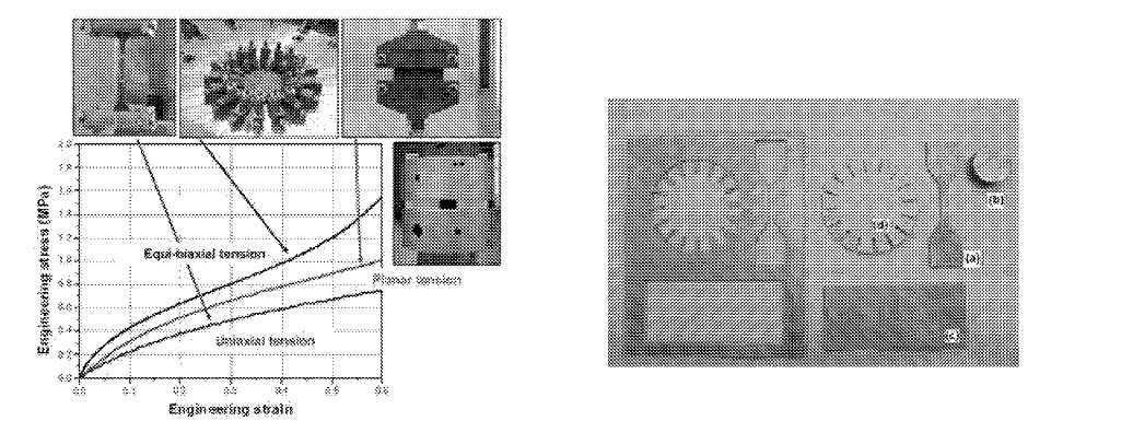
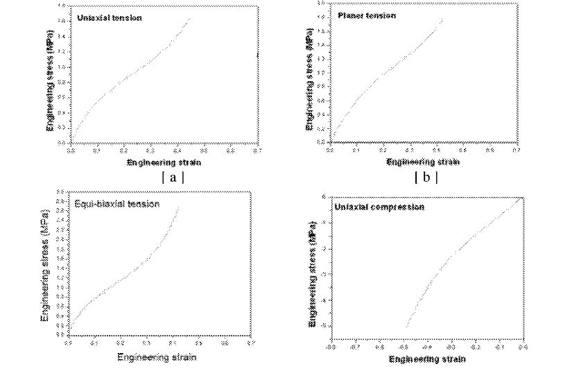
Fig. 6 The stress-strain curves of rubber material
(a) Uniaxial tension (b) Planer tension
(c) Equi-biaxial tension (d) Uniaxial compression
2.2. Static material property test of the diaphragm [2]
The non-linear rubber properties of Mooney-Rivlin factor (CI, C2) are applied to finite element analysis. The non-linear material factor is calculated by experimental stress and strain curve. The material property test of rubber is conducted by using uni-axial tension test, compression test, planer tension test and equi-biaxial tension test. Fig. 4 shows a material test of rubber specimen and stress-strain curves. Fig. 5 shows the shape of the test specimen and rubber sheet for static material property test. The applied extension speed is 50 mm/min
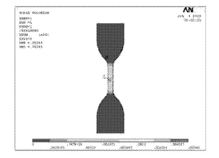
2.3. Verification of finite element analysis
The structural analysis of uni-axial tension specimen is conducted. The FEM analysis was conducted with the same boundary condition of the experiment. The FEM analysis is carried out by commercial FEM code, ANSYS 8.0. From the FEM analysis, the stress is
1.2 MPa at stain 0.34. The analysis results are similar to test results. As the results, the experimental stress is 1.2 MPa at strain 0.32. Therefore, the validity of FEM analysis is verified.
2.4. Structural analysis of diaphragm with a constant thickness
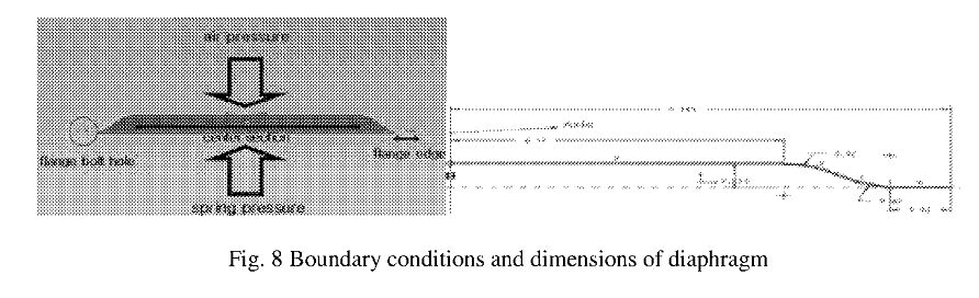
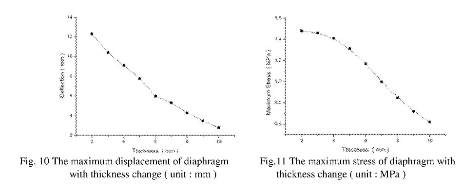
The stress analysis of diaphragm is carried out by FEM. The boundary condition of the diaphragm is shown in Fig. 8. In the FEM analysis, the Hyper 58 element was used in the analysis. The considered thickness and air pressures are 2~10mm and 0.1 MPa, respectively. The analysis results of the diaphragm with thickness 2 mm are shown in Fig. 9. The maximum stress happened at flange edge part and maximum displacement happened between flange edge and spring support.
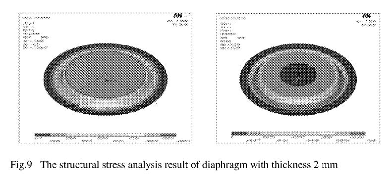
Analysis results about maximum stress and maximum displacement of the diaphragm with thickness change are presented in Fig. 10 and Fig. 11. As thickness increases, deflection is decreased rapidly. However, maximum stress is increased as thickness is decreased.
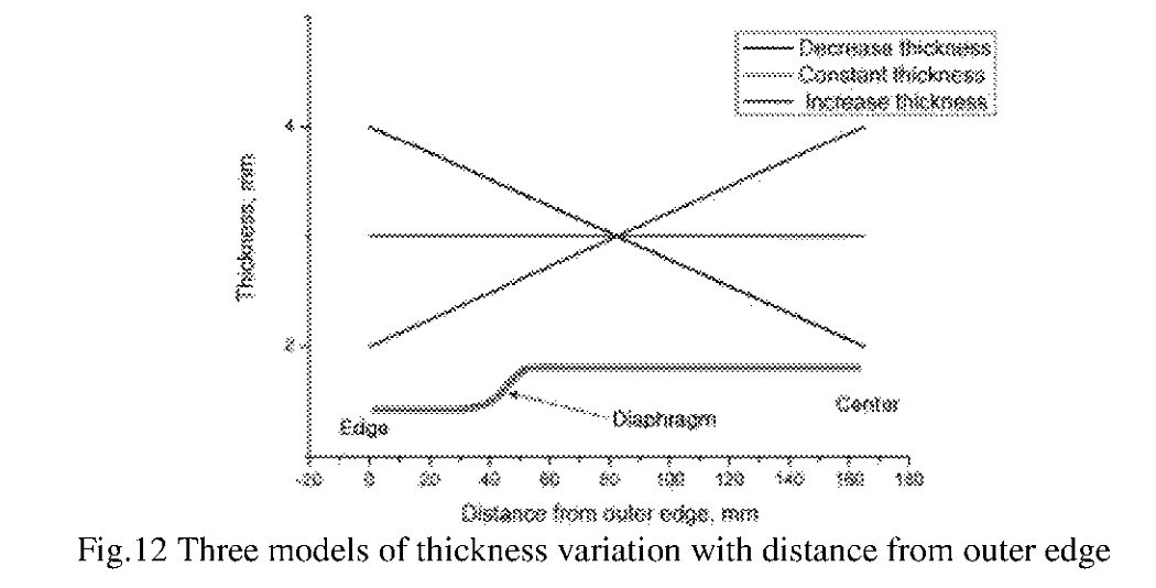
2.5. Structural analysis of diaphragm with a variable thickness
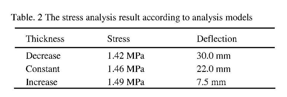
The analysis was conducted with following three models. The first model is decreasing thickness; that is, edge thickness is larger than the center. The second model is the constant thickness; that is, the thickness of center and edge are same. The third model is increasing thickness; that is, edge thickness is thinner than the center. The analysis result for three models is presented
3. Conclusions
The structural analysis of uni-axial tension specimen that has equal boundary condition with the test is carried out by FEM. Therefore, this study obtained effectiveness of analysis method. From the FEM analysis results, the maximum stress happened at flange edge part and maximum displacement happened between flange edge and spring support. As the diaphragm thickness increases, the maximum deflection decreases. Even if a section area is same, the maximum stress is varied with the thickness of edge side. In case of same section area, the maximum stress of strengthening edge side is lower than that of constant thickness.
